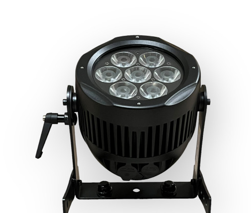
Model LV-7 Battery LED Tour Par IPEdition EN · 04 / 2026 · V1Dokument-Nr. LV7-EN-01
Battery LED Par IP65
LV-7 Battery
Battery-powered tour par with 7 × 10 W RGBW 4-in-1 LEDs, up to 20 hours runtime, W-DMX, IR remote, frost filter and IP65 protection
Operating manual. Please read in full before first use and keep for future reference.
Light source
7 × 10 WRGBW 4-in-1
Battery runtime
up to 20 hLi-Ion
DMX channels
2–125 channel modes
IP rating
IP65Outdoor
Lexvision LV-7 Battery IPForeword · About this document
Foreword
00Welcome
Thank you for purchasing the Lexvision LV-7 Battery. All fixtures are checked before shipping and leave the factory in excellent operating condition.
First check the shipping carton for transport damage, then check the fixture itself for integrity and correct operation. If damage is found, parts are missing or the fixture works abnormally, contact the manufacturer for further instructions — do not return the fixture to the dealer before contacting us.
0.1Operating and Channel Modes
The LV-7 offers three operating modes: DMX mode, Auto mode and Master/Slave mode, plus five DMX channel modes with 2, 3, 4, 9 and 12 channels. Several fixtures can be linked: one fixture in Auto mode, all others in Master/Slave mode — the slave fixtures then follow the master.
Before you operate this unit read the manual carefully. Always include the manual if you pass, rent or sell the unit to another user. This manual cannot address all possible dangers and environments — please use your own caution when operating. This product is for professional use only, not for household use.
Electrical SafetyOnly qualified personnel may repair this product. Do not open the product housing. Do not apply power if the light is damaged. Always follow local safety requirements.
Do not operate the unit in areas of high temperature conditions. It will cause abnormal function or damage the product.
Always use a suitable safety wire when mounting the light overhead, and connect the safety wire only to the intended safety mount.
Do not directly look into the light — it can cause harm to your eyes. Do not look at the LEDs with a magnifying glass or any other optical instrument that may concentrate the light output.
The exterior surfaces of the light can become hot, up to 70 °C during normal operation. Ensure that accidental physical contact with the device is impossible.
Install only in ventilated locations; do not cover the light.
Always charge with the flight case open. It is recommended to charge at a temperature between 15 °C and 35 °C.
The light contains a lithium ion battery. Do not throw the unit into the garbage at the end of its lifetime — dispose of it according to your local ordinances and regulations to avoid polluting the environment. The packaging is recyclable.
Lexvision LV-7 Battery IP01.1 · Li-Ion Battery
1.1Li-Ion Battery
A rechargeable lithium ion battery is built into this unit.
Risk of Fire and ExplosionDo not place the battery in fire or heat. Do not use or charge the light if it is damaged. Avoid bumping or plunging, it may cause fire or explosion.
Only authorized personnel may service the battery.
Never store the battery when fully drained; always recharge immediately when empty.
Make sure to fully charge all units before storing them — partially charged batteries will lose capacity.
The battery may only be replaced with an original spare part.
Charging BehaviourThe fixture will only commence charging when its battery has a temperature of 45 °C or less. If the fixture is too warm, turn it off and let it cool down; once cold enough, it will start charging.
Lexvision LV-7 Battery IP02 · Technical Data
Chapter 02
02Technical Data
Light Source & Optics
LED source
7 × 10 W high-power LED, RGBW 4-in-1
Optics
7 × high-efficiency acrylic lens 15°
Filters
Frost filter (supplied) · diffuser optional
Light effects
Color mixing, variable color change, strobing, dimmer, fading
Passive, temperature-regulated, with over-temperature protection
Operating temperature
−20 °C to 45 °C
Mounting
2 × quarter-turn fastening for omega clamps · 1 × safety attachment point
Dimensions
249 × 210 × 264 mm
Weight
5,6 kg net
Lexvision LV-7 Battery IP03 · Mounting
Chapter 03
03Mounting
The mounting point must safely bear the weight of the fixture; the fixture must additionally be secured with a suitable safety cable of sufficient load rating in accordance with local regulations and laws. The unit must be secured with a secondary safety attachment, e.g. an appropriate safety cable.
Never stand directly below the unit when mounting, removing, or servicing the unit.
Overhead mounting requires extensive experience, including calculating working load limits, the installation material being used, and periodic safety inspection of all installation material and the unit. If you lack these qualifications, do not attempt the installation yourself.
The installation should be checked by a skilled person once a year.
The fixture is fully operational in three different mounting positions: hanging upside-down from a ceiling, set on a flat level surface, or mounted on its side.
Keep the fixture at least 0.5 m away from any flammable materials (decoration etc.).
Use and install the supplied safety cable as a safety measure to prevent accidental damage and/or injury in the event the clamp fails.
Cabling must have a male XLR connector on one end and a female XLR connector on the other end.
Conductor
3-pin female (output)
5-pin male (input)
Ground / shield
Pin 1
Pin 1
Data (−) signal
Pin 2
Pin 2
Data (+) signal
Pin 3
Pin 3
Do not use
—
Pin 4 / Pin 5
No Ground LoopDo not allow contact between the signal ground and the chassis ground of the fixture — grounding the ground can cause a ground loop and the fixture may perform erratically. Test cables with an ohm meter to verify polarity and to make sure the pins are not grounded or shorted to the shield or each other.
If you use a controller with a 5-pin DMX output connector, you need a 5-pin to 3-pin adapter.
4.2W-DMX (Wireless DMX)
Connecting: Press "ENTER", scroll with "UP"/"DOWN" to SET UP, press "ENTER", then scroll to Wireless rel and press "ENTER". Then switch to DMX mode. Once the wireless icon shows green, the W-DMX connection is established — green means successful, red means not connected.
Releasing the wireless signal: Press "ENTER" until Wireless rel is shown, press "ENTER" until "press +/−" is displayed, then press and hold "UP" or "DOWN" for about 5–6 seconds until the display changes from "Initialization" to "Release finish" — the signal has been released successfully.
Note: the wireless controller should be hung in a good position; the antenna of the fixture should face the controller. The usable range is up to 200 m.
Lexvision LV-7 Battery IP05 · Display & IR Remote
Chapter 05
05Display & IR Remote
5.1Display Indicators
Item
Meaning
1
Operating mode — "DMX" in DMX mode, "SLAVE" in slave mode
2
Condition of signal transmission — green = connected, red = disconnected
3
Temperature of the fixture
4
Selectable menu items
5
Key lock — "Key lock open" = on, "Key lock off" = off
6
Condition of the wireless signal — green = connected, red = disconnected
7
Battery charge level
While the battery is charging, the indicator runs from empty to full; once charging stops, the current charge level is shown. If the text changes from white to yellow, the configured maximum temperature has been exceeded — the fixture then regulates its operating temperature automatically. An "Error" display indicates a temperature problem.
5.2IR Remote
Button
Function
Power on/off
Switch the fixture on and off
DMX
Control the DMX address; double click switches to channel mode
SLAVE
Master/slave mode
AUTO 1 / AUTO 2
Automatic mode
SOUND 1 / SOUND 2
Without function
UP / DOWN
Choose the program or numerical value required
STROBE
Strobe
0 – 9
Adjust numerical values in any program mode
SPEED
Speed adjustment
R / G / B / W
Color choosing
Lexvision LV-7 Battery IP06 · Menu Structure (1/2)
Chapter 06
06Menu Structure
Menu item
Description
DMX
Connect several fixtures with DMX cable and control them from a console. Submenus: CHANNEL — select the channel mode (2/3/4/9/12 CH) · ADDRESS — select the start address 001–512.
RUN MODE
Select DMX or SLAVE. In slave mode the fixture follows the fixture configured as master.
AUTO
AUTO MODE — select the desired auto mode · SPEED — select the desired running speed.
CUSTOMER
Select one of the 11 custom programs edited in the "EDIT" menu.
CAL WHITE
Adjust the values of the 11 white colors — each editable via "Red", "Green", "Blue" and "White".
STAT COLOR
Set a static color and strobe: STAT RED / STAT GREEN / STAT BLUE / STAT WHITE — brightness per color · SELECT COLOR — select one of 52 static colors · STAT STROB — strobe speed.
EDIT
Edit custom programs PR.01 to PR.11, 32 scenes each (SC-01 to SC-32). Editable parameters per scene: RED (0–255), GREEN (0–255), BLUE (0–255), WHITE (0–255), FADE (0–31), FLASH (0–50), STROBE (0–31), TIME (0–100). Save by holding ENTER for 5 seconds.
UPLOAD
Transfer custom programs from the master fixture to all slave fixtures. First set the fixture holding the program to master mode and all others to slave mode, connect all fixtures with DMX cables, then select "UPLOAD" on the master and press ENTER.
RESET
Reset all values of the system (factory reset).
Lexvision LV-7 Battery IP06 · Menu Structure (2/2)
6.1SET UP — Settings
Option
Description
ID Number
Select the ID number (001–066 or OFF). Then set channel 11 to the corresponding value range to control the fixture individually from the console.
Display Led / LCD Black
"ON" — the display stays on permanently · "OFF"/"30s" — the display switches off after about ten or thirty seconds.
Key Lock
Key lock on/off. The password is [DOWN] + [UP] + [DOWN] + [UP]. With the lock active, the password must be entered before pressing any button.
Max Temp
Set the maximum working temperature (default 70 °C). If exceeded, the "Temp xx" display changes from white to yellow and the fixture adjusts its working temperature automatically.
Dimmer RED / GREEN / BLUE / WHITE / ALL
Adjust brightness per color channel or for all channels together (000–255).
Dimmer Curve
Curve 1 – Curve 4
Rate
600 / 1200 / 2400 / 4800 / 9600 Hz
Remote
IR remote ON / OFF
Wireless
W-DMX ON / OFF · "Wireless rel" to connect or release (see chapter 4.2)
DMX State
Blackout — output goes dark when the signal is lost · DMX Hold — hold the last value
Factory Reset
Restore factory settings
6.2INFORMATION
Option
Description
Software-Ver
Software version (e.g. V1.0)
Hardware-Ver
Hardware version (e.g. V1.1)
Fix Times / Working Time
Working hours of the fixture
RDM UID
RDM device identifier
Lexvision LV-7 Battery IP07.1 · 2, 3 and 4-Channel Mode
Chapter 07
07DMX Channel Charts
The LV-7 offers five channel modes with 2, 3, 4, 9 and 12 channels. The following chapters list each mode in full; the extensive color, white, AUTO and ID tables are collected in their own subchapters.
7.12-Channel Mode
CH
Function
Range / Description
01
Color macro
000 – 255 · 52 colors, see chapter 7.4
02
White preset
000 – 255 · 11 white tones, see chapter 7.5
7.1.13-Channel Mode (HSV)
CH
Function
Range / Description
01
Hue (hue)
000 – 255
02
Saturation (saturation)
000 – 255
03
Value (brightness)
000 – 255
7.1.24-Channel Mode (RGBW)
CH
Function
Range / Description
01
Red
000 – 255 · red LED dimmer from low to high
02
Green
000 – 255 · green LED dimmer from low to high
03
Blue
000 – 255 · blue LED dimmer from low to high
04
White
000 – 255 · white LED dimmer from low to high
Lexvision LV-7 Battery IP07.2 · 9-Channel Mode
7.29-Channel Mode
CH
Function
Range / Description
01
Master dimmer
000 – 255
02
Strobe
000–009 OFF
010–255 Strobe from slow to fast
03
Red
000 – 255
04
Green
000 – 255
05
Blue
000 – 255
06
White
000 – 255
07
Dimmer speed
000 – 255
08
AUTO program see chapter 7.5
000–007 OFF
008–023 AUTO 1
024–039 AUTO 2
040–055 AUTO 3
056–071 AUTO 4
072–087 AUTO 5
088–103 AUTO 6
104–119 AUTO 7
120–129 AUTO 8
130–151 AUTO 9
152–168 AUTO 10
169–183 AUTO 11
184–199 AUTO 12
200–255 AUTO 13
09
AUTO speed
000 – 255 · speed from slow to fast
Lexvision LV-7 Battery IP07.3 · 12-Channel Mode
7.312-Channel Mode
CH
Function
Range / Description
01
Master dimmer
000 – 255
02
Strobe
000–009 OFF
010–255 Strobe from slow to fast
03
Red
000 – 255
04
Green
000 – 255
05
Blue
000 – 255
06
White
000 – 255
07
Dimmer speed
000 – 255
08
Color macro
000 – 255 · 52 colors, see chapter 7.4
09
White preset
000 – 255 · 11 white tones, see chapter 7.5
10
AUTO program
000 – 255 · OFF, AUTO 1 – AUTO 13, see chapter 7.5
11
ID address set
000 – 255 · 66 ID addresses, see chapter 7.6
12
Speed
000 – 255 · speed from slow to fast
Color Macro and White PresetChannels 08 and 09 in 12-channel mode correspond exactly to channels 01 and 02 of the 2-channel mode. The full value tables therefore apply to both modes.
Lexvision LV-7 Battery IP07.4 · Color Macros (1/2)
7.4Color Macros — 52 Colors (1/2)
Applies to channel 01 in 2-channel mode and channel 08 in 12-channel mode. The color names are taken verbatim from the manufacturer; no RGBW target values are published for these colors.
DMX value
Color
000–010
none
011–016
none
017–023
none
024–027
red
028–031
green
032–035
blue
036–039
yellow
040–043
cyan
044–047
magenta
048–051
white
052–055
orange
056–059
pink
060–063
violet
064–067
aquamarine
DMX value
Color
068–071
sky blue
072–075
full white
076–079
cool white
080–083
warm white
084–087
white 3200
088–091
white 2500
092–095
yellow 2
096–099
straw
100–103
orange 2
104–107
light rose
108–111
dark pink
112–115
magenta 2
116–123
med blue green
124–127
blue 2
Lexvision LV-7 Battery IP07.4 · Color Macros (2/2)
7.4Color Macros — 52 Colors (2/2)
DMX value
Color
128–131
bright pink
132–135
medium blue
136–139
golden amber
140–143
deep golden amber
144–147
pale lavender
148–151
apricot
152–155
med blue red
156–159
chocolate
160–163
just blue
164–167
surprise pink
168–171
scarlet
172–175
surprise peach
176–179
light peach
DMX value
Color
180–183
warm white 2
184–187
mauve
188–191
bright blue
192–195
alice blue
196–199
rose indigo
200–203
urban blue
204–207
cool blue
208–211
light salmon
212–215
mayan sun
216–219
cherry rose
220–222
flesh pink
223–255
skelton exotic sangria
Lexvision LV-7 Battery IP07.5 · White Presets & AUTO Programs
The eleven white tones correspond to the presets of the CAL WHITE menu, where each can be individually calibrated via its red, green, blue and white values. The color temperatures shown are the target values of the 2500 K to 10000 K series held in the menu.
Up to 66 separate ID addresses can be assigned per DMX start address. Activate ID addressing in the menu via SET UP → ID Number and set an incremental value in each fixture. With channel 11 at 000–009 the whole group at that DMX address is controlled collectively; setting one of the ID values addresses that single fixture only.
Value
ID
000–009
all IDs
010–019
ID 1
020–029
ID 2
030–039
ID 3
040–049
ID 4
050–059
ID 5
060–069
ID 6
070–079
ID 7
080–089
ID 8
090–099
ID 9
100–109
ID 10
110–119
ID 11
120–129
ID 12
130–139
ID 13
140–149
ID 14
150–159
ID 15
160–169
ID 16
170–179
ID 17
180–189
ID 18
190–199
ID 19
200–209
ID 20
210
ID 21
211
ID 22
Value
ID
212
ID 23
213
ID 24
214
ID 25
215
ID 26
216
ID 27
217
ID 28
218
ID 29
219
ID 30
220
ID 31
221
ID 32
222
ID 33
223
ID 34
224
ID 35
225
ID 36
226
ID 37
227
ID 38
228
ID 39
229
ID 40
230
ID 41
231
ID 42
232
ID 43
233
ID 44
Value
ID
234
ID 45
235
ID 46
236
ID 47
237
ID 48
238
ID 49
239
ID 50
240
ID 51
241
ID 52
242
ID 53
243
ID 54
244
ID 55
245
ID 56
246
ID 57
247
ID 58
248
ID 59
249
ID 60
250
ID 61
251
ID 62
252
ID 63
253
ID 64
254
ID 65
255
ID 66
Lexvision LV-7 Battery IP08 · Troubleshooting
Chapter 08
08Troubleshooting
Symptom
Approach
The fixture does not turn on
The battery may be empty. Connect it to the power cable and try again.
The fixture turns on and the display is on, but the LEDs do not emit light
The fixture could be set to BLACKOUT mode, or set to DMX Hold without receiving a valid signal. It is good practice to do a factory reset.
The fixture does not display the color or effect chosen
The fixture may still be operating under a previous setting. It is good practice to do a factory reset.
After completing a reset, the fixture still cannot be controlled
Turn the light off and on again. If it still cannot be controlled, consult authorized personnel.
The fixture does not run long enough on battery
The required RUNTIME can be set and defaults to several hours — set RUNTIME to the required value to achieve a greater battery runtime. Alternatively program the fixture to display only colors that use less power, such as red, green, blue and white. Note also that runtime is reduced slightly if the battery is very cold.
The power cable is connected but the fixture is not charging
The battery may be fully charged. Charging also only commences when the battery temperature is 45 °C or less — turn the fixture off and let it cool down. If it still does not charge, consult authorized personnel.
Lexvision LV-7 Battery IP— · CE Compliance Notice
Appendix
—CE Compliance Notice
The manufacturer declares under its sole responsibility that the LV-7 Battery complies with the relevant EU harmonization legislation.
EU Declaration of Conformity
A signed EU Declaration of Conformity exists for this product. It is not part of this manual and can be requested from us at any time — by email to verkauf@lexvision.de or by phone on +49 (0) 651 14567727, stating the product designation.
The signed EU Declaration of Conformity for this product is available upon request from Lexvision GmbH, Waldweg 26, 54636 Sefferweich, Germany.